5G NR Throughput Calculator
Estimate theoretical 5G NR downlink and uplink throughput with carrier aggregation, NRB tables, MIMO layers, modulation, code rate, scaling factor, and TDD slot split.
Carrier Setup
Adjust parameters and calculate.
Total Throughput
Carrier Breakdown
| Carrier | FR | Duplex | BW / SCS | NRB | DL Share | UL Share | DL Throughput | UL Throughput |
|---|---|---|---|---|---|---|---|---|
| No calculation yet. | ||||||||
Report an Issue or Suggest an Improvement
Found a calculation issue, formatting bug, missing band, or have an idea to improve 5G NR Throughput Calculator? Please let us know.
Calculation Notes
- NRB table: based on common NR channel bandwidth / SCS combinations for FR1 and FR2.
- Formula: throughput = layers × modulation order × scaling factor × code rate × NRB × 12 × 14 × slots/s × (1 - overhead) × duplex share.
- TDD split: downlink and uplink share are derived from configured DL, UL, and flexible slot symbols.
- SDL/SUL: supplemental downlink disables UL throughput, supplemental uplink disables DL throughput.
- Code rate: default is the commonly used peak assumption of 948/1024 = 92.578%.
- Extended coverage: includes FR1 35 MHz and 45 MHz bandwidths, plus 1024QAM where the device and network support it.
How to calculate the theoretical data rate in 5G NR for uplink and downlink?
Throughput estimation is not straightforward, and it cannot be determined accurately using a single simple equation.
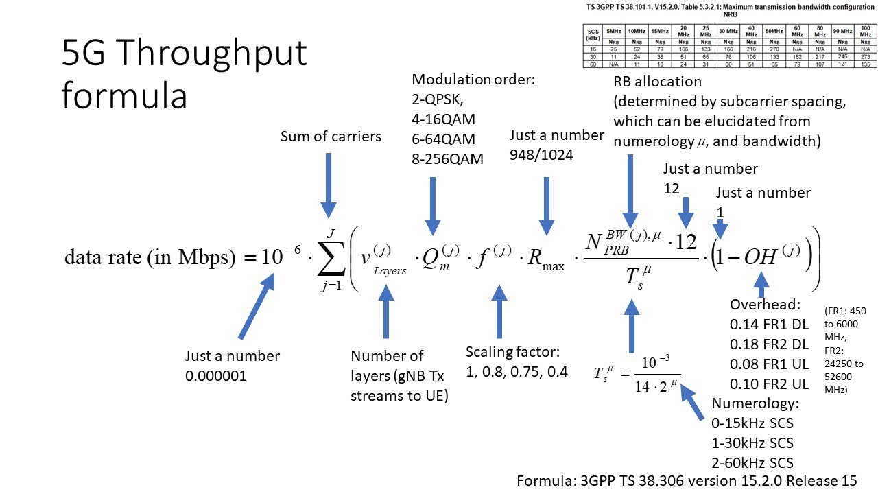
3GPP TS 38.306 provides a formula for calculating the maximum downlink and uplink data rate that a UE can support. The formula includes Carrier Aggregation (CA), with the calculation performed separately for each component carrier (CC) and then summed across J carriers.
Among the constants in the formula, 10-6 converts the final result to Mbps. Rmax is 948/1024, which represents the maximum LDPC coding rate. The value 12 refers to the number of subcarriers in one Resource Block (RB). This is multiplied by NBWPRB, which is the maximum number of RBs that can be allocated to the UE for a given subcarrier spacing (SCS) and channel bandwidth. The formula assumes a normal cyclic prefix.
The number of layers corresponds to the number of MIMO layers. The modulation order, Qm, defines how many bits are carried by each symbol. Its values are 1, 2, 4, 6, and 8, corresponding to BPSK, QPSK, 16QAM, 64QAM, and 256QAM, respectively.
The total number of bits is then divided by the symbol time, Ts. With 15 kHz SCS, a slot contains 14 OFDM symbols and has a duration of 1 ms. As the SCS increases, the slot duration decreases proportionally, which leads to higher achievable data rates.