5G NR Transport Block Size Calculator
Calculate 5G NR transport block size for both downlink and uplink using the latest 3GPP NR TBS procedure from TS 38.214 Release 18.
Transport Block Inputs
Adjust the parameters and calculate.
Result
Calculation Details
| Field | Value |
|---|---|
| No calculation yet. | |
Report an Issue or Suggest an Improvement
Found a calculation issue, formatting bug, missing band, or have an idea to improve 5G NR Transport Block Size Calculator? Please let us know.
How to Use This Tool
- Select Downlink for PDSCH or Uplink for PUSCH.
- Choose the applicable MCS table and MCS index. The tool will show the resulting modulation order and target code rate.
- Enter the scheduled PRBs, number of allocated symbols, and the total DM-RS RE per PRB.
- Set xOverhead if the configuration uses one of the standardized overhead values.
- For UL, enable transform precoding if needed. For the transform-precoded low-index cases, you can also enable pi/2-BPSK.
- Use TB Scaling only for the downlink RNTI cases that apply transport block scaling; otherwise keep it at 1.
- Press Calculate TBS and review the result and intermediate values.
Method Notes
- Specification basis: TBS determination follows TS 38.214 Release 18 clause 5.1.3.2 for DL and clause 6.1.4.2 for UL.
- RE cap: total RE uses
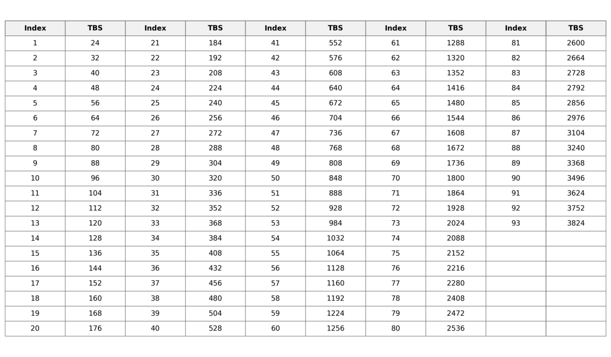
min(156, NRE')per PRB, as specified. - Small TBS branch: when
Ninfo ≤ 3824, the calculator uses the standardized TBS lookup table. - Large TBS branch: when
Ninfo > 3824, the calculator uses the quantization and code-block-aware rounding defined in the spec. - Per-TB scope: this calculator computes one transport block. For dual-codeword scheduling, calculate each codeword transport block with its own parameters.
- UL tables: transform-precoded PUSCH uses the dedicated UL MCS tables, including the pi/2-BPSK-dependent low-index rows.
What Is Transport Block Size (TBS) in 5G?
A transport block (TB) is the unit of data exchanged between the MAC layer and the physical layer. At the transmitter, the transport block is passed from MAC to PHY, processed by the physical layer, and then mapped onto the PDSCH for transmission over the air interface. At the receiver, the reverse process takes place. Before the UE can decode data carried on the PDSCH, it must first determine the transport block size (TBS).
To calculate the TBS, the UE uses a combination of semi-static information provided through RRC signaling and dynamic scheduling information carried in the Downlink Control Information (DCI) on the PDCCH.
The first step is to determine the number of resource elements available for data transmission within a single resource block. In 3GPP TS 38.214, this is defined as:

The resulting N′RE value is then multiplied by the number of allocated resource blocks to obtain NRE, which represents the total number of resource elements available for data transmission across the scheduled bandwidth. The number of allocated resource blocks is also obtained from the DCI on the PDCCH.
Next, the UE converts the available resource elements into a number of information bits using the 3GPP-defined equation:
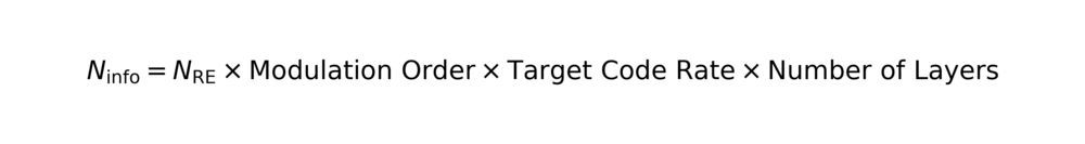
The modulation order and target code rate are taken from the selected MCS table. The table itself is determined by a combination of RRC signaling and physical-layer signaling, while the MCS field in the DCI selects the specific row. A higher modulation order means that each resource element carries more bits. A higher target code rate means less redundancy is added by channel coding, leaving more capacity for payload bits.
The number of layers depends on the DCI format. When the PDSCH allocation is received using DCI Format 1_0, the number of layers is fixed to 1. When DCI Format 1_1 is used, the number of layers is derived from the DMRS Ports field in the corresponding antenna-port lookup table. In that case, the number of layers equals the number of allocated DMRS ports.
For paging messages and random access responses, an additional scaling factor may be applied to Ninfo. This applies when PDSCH resources are allocated using DCI Format 1_0 with the P-RNTI or RA-RNTI. The scaling factor is determined by the Transport Block Scaling field in the DCI. Values such as 0.5 or 0.25 reduce the resulting TBS, which lowers the effective coding rate and improves transmission reliability by adding more redundancy.
The remaining steps depend on the value of Ninfo. If Ninfo is less than 3824 bits, one procedure is used. Otherwise, a different procedure applies. This threshold is tied to LDPC processing limits. In particular, 3824 bits is related to the maximum code block size of 3840 bits for LDPC Base Graph 2 after adding a 16-bit CRC. For transport blocks below this threshold, segmentation is not required before channel coding. Larger transport blocks may require segmentation before LDPC encoding.
Finally, the UE selects the smallest standardized transport block size from the TBS table that is greater than or equal to the calculated Ninfo. That value becomes the transport block size used for decoding.
Here, N′RE is the number of resource elements per resource block available for data transmission. Nshsymb is the number of OFDM symbols allocated to the UE within the slot, obtained from the DCI as part of the PDSCH resource allocation. NPRBDMRS is the number of resource elements per resource block reserved for DMRS. This also reflects the impact of DMRS allocated to other UEs in multi-user MIMO scenarios, based on the relevant antenna port configuration. NPRBoh represents any additional overhead that reduces the number of resource elements available for data, such as CSI-RS. The gNB signals this overhead using the xOverhead / xOh-PDSCH RRC parameter. Possible values are 0, 6, 12, or 18 resource elements, and the UE assumes 0 if the parameter is not provided.
If the calculated value of N′RE is greater than 156, it is capped at 156. Although a resource block contains 12 × 14 = 168 resource elements with a normal cyclic prefix, not all of them are assumed to be available for data.