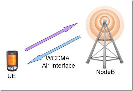
Wideband Code Division Multiple Access (WCDMA) is the physical layer used for Universal Terrestrial Radio Access (UTRA) FDD mode. The WCDMA technology provides the UMTS system some of the new functionalities on the air interface.
The main features provided by WCDMA physical layer are:
- Spreading and Scrambling
- Transport Channel Combining
- Soft Handover
- Compressed Mode
- Power Control
Spreading and Scrambling
Scrambling
The concept of scrambling was introduced in CDMA systems before it was implemented in WCDMA. Scrambling is used to separate the base stations or UEs from each other.
Channelisation Code
Transmissions from a single source are separated by channelisation codes. The examples can be :
– In the downlink it can be used to separate different connections from the same sector.
– In the uplink it can be used to separate different dedicated physical channels from each other, e.g. separating DPDCH from DPCCH.
The spreading and channelisation codes are based on Orthogonal Variable Spreading Factor (OVSF).
More about OVSF can be found in the following link:
Transport Channel Combining
Another new feature in WCDMA air interface to combine different services together. This may be Voice service with PS bearer service.
The physical layer receives data from different sources. All these data streams can differ from each other in terms of data rate and reliability. The objective of the transport channel combiner is to bring together all the data streams from higher layers, changing them when appropriate and then multiplex them onto physical channel.
Changing the data rate of individual channels is the job of the rate matcher. The rate matcher works with the instructions from the RNC. The change in data rate can be achieved either through puncturing or repetitions.
Soft Handover
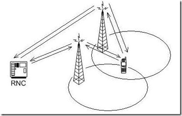
Soft Handover is a handover in which the mobile station starts communication with a new Node-B on a same carrier frequency, or sector of the same site (softer handover), performing utmost a change of code.
There are areas of the UE operation in which the UE is connected to a number of Node-Bs.
Active Set: It is defined as the set of Node-Bs the UE is simultaneously connected to.
The Soft Handover procedure is composed of a number of single functions:
– Measurements;
– Filtering of Measurements;
– Reporting of Measurement results;
– The Soft Handover Algorithm;
– Execution of Handover.
Compressed Mode
If a UE need to perform a handover to a UMTS cell on different frequency or to a different system on a different frequency, it will need to make measurements on the target cells. To do this job compressed mode technique is used in UMTS. Compressed mode inserts an artificial gap in transmission in either the uplink or the downlink. During this gap UE is able to switch to the other frequency, make a measurement and come back to the original frequency.
The UE capabilities define whether a UE requires compressed mode in order to monitor cells on other FDD frequencies and on other modes and radio access technologies. UE capabilities indicate the need for compressed mode separately for the uplink and downlink and for each mode, radio access technology and frequency band.
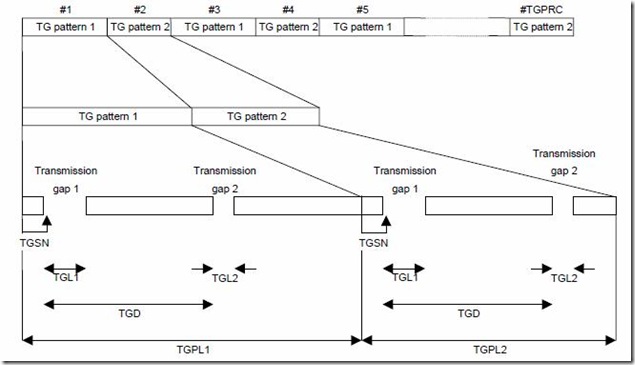
The following parameters characterise a transmission gap pattern:
TGSN (Transmission Gap Starting Slot Number): A transmission gap pattern begins in a radio frame, henceforward called first radio frame of the transmission gap pattern, containing at least one transmission gap slot. TGSN is the slot number of the first transmission gap slot within the first radio frame of the transmission gap pattern;
TGL1 (Transmission Gap Length 1): This is the duration of the first transmission gap within the transmission gap pattern, expressed in number of slots;
TGL2 (Transmission Gap Length 2): This is the duration of the second transmission gap within the transmission gap pattern, expressed in number of slots. If this parameter is not explicitly set by higher layers, then TGL2 = TGL1;
TGD (Transmission Gap start Distance): This is the duration between the starting slots of two consecutive transmission gaps within a transmission gap pattern, expressed in number of slots.
TGPL1 (Transmission Gap Pattern Length): This is the duration of transmission gap pattern 1, expressed in number of frames;
TGPL2 (Transmission Gap Pattern Length): This is the duration of transmission gap pattern 2, expressed in number of frames. If this parameter is not explicitly set by higher layers, then TGPL2 = TGPL1.
The following parameters control the transmission gap pattern sequence start and repetition:
TGPRC (Transmission Gap Pattern Repetition Count): This is the number of transmission gap patterns within the transmission gap pattern sequence;
TGCFN (Transmission Gap Connection Frame Number): This is the CFN of the first radio frame of the first pattern 1 within the transmission gap pattern sequence.
Power Control
Uplink Power Control
The uplink power control has two parts:
- Inner loop
- Outer loop
Inner loop power control
For inner loop power control the UE transmits to the NodeB. The NodeB receives the Signal to Interferance Ration (SIR) and compares it with the target. Based on the target level the NodeB instruct the UE to increase or decrease power. This process occurs for every transmission slot (every 667 micro second).
SIRest > SIRtarget TPC = 0
SIRest < SIRtarget TPC = 1
Outer loop power control
The outer loop power control ensures the QoS for a particular UE. The outer loop power control is between the NodeB and RNC.
To achieve this objective NodeB sends quality information to the RNC. The quality information is based on BER and Block Error Rate (BLER) for a specific UE. Based on this info RNC decides whether to increase or decrease the quality of the radio link.
Downlink Power Control
Power control on the downlink is same as that of the uplink except that the roles of Nodeb and UE are switched.
References
Physical layer procedures (FDD): 3GPP TS 25.214
Physical layer – Measurements (FDD): 3GPP TS 25.215
Radio resource management strategies: 3GPP TR 25.922


Permalink
very good job wonderful would ebe great to share knowledge with you , i habve been working in wireless for past 10 yrs .
GRRRT
BR
Prashant
Permalink
very good job wonderful would ebe great to share knowledge with you , i habve been working in wireless for past 10 yrs .
GRRRT
BR
Prashant
Permalink
Muy buena la información, pero no solo es teoría, como podríamos tener un contacto más cerca con lo aplicativo??
Ejemplo: algunos software, equipos actuales en los nodos B, etc.…
Saludos
Permalink
Muy buena la información, pero no solo es teoría, como podríamos tener un contacto más cerca con lo aplicativo??
Ejemplo: algunos software, equipos actuales en los nodos B, etc.…
Saludos
Permalink
Very good information, but it is not only theory, we could have a closer contact with the applied?
Example: some software, existing equipment at nodes B, etc.. …
Greetings
Permalink
Very good information, but it is not only theory, we could have a closer contact with the applied?
Example: some software, existing equipment at nodes B, etc.. …
Greetings
Permalink
good basics of WCDMA.
Permalink
good basics of WCDMA.
Permalink
Hi,
Good vital data s in WCDMA . Clear to understand…
Permalink
Hi,
Good vital data s in WCDMA . Clear to understand…
Permalink
Nice site, nice and easy on the eyes and great content too.