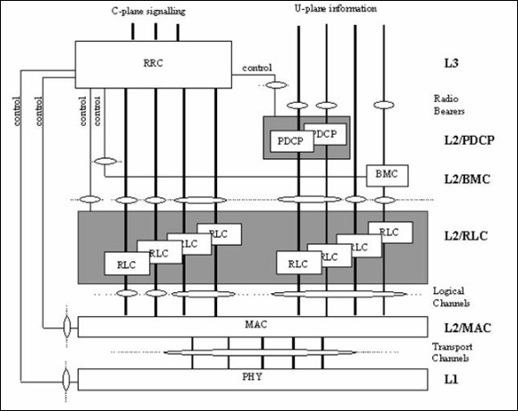
Radio Interface Architecture
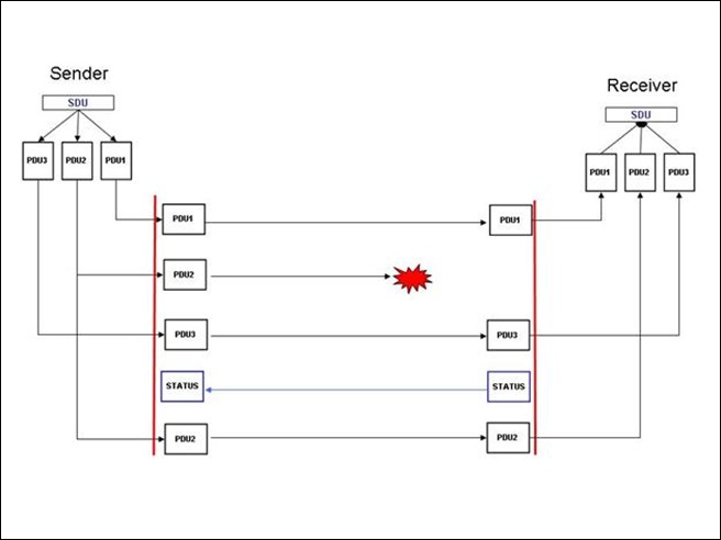
Why RLC is required?
- Larger pieces of data are not suitable to be sent over the air interface where bit faults are common.
- Smaller pieces can be individually retransmitted
- Retransmissions on higher Protocol level take too long time. Therefore it is better to have the retransmission as close to the biggest trouble source (i.e. The radio interface)
RLC main functionalities
- Segmentation and reassembly.
- Concatenation.
- Padding.
- Transfer of user data.
- Error correction.
- In-sequence delivery of upper layer PDUs.
- Duplicate detection.
- Flow control.
- Sequence number check.
- Protocol error detection and recovery.
- Ciphering.
- SDU discard.
- Out of sequence SDU delivery.
- Duplicate avoidance and reordering.
Data flow between layers
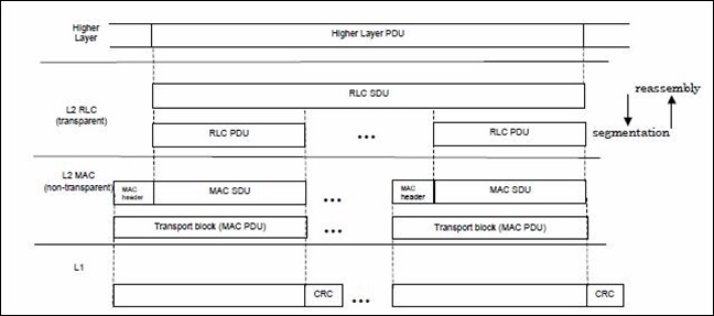
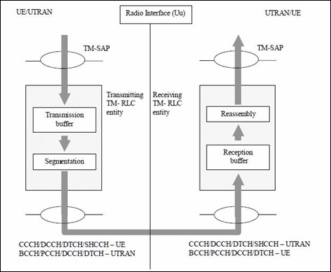
Data flow for transparent RLC
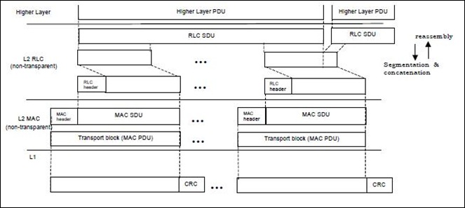
Data flow for non-transparent RLC
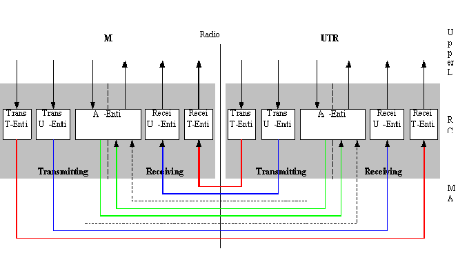
Model of RLC Sublayer
- TM (Transparent mode)
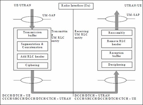
- UM (Unacknowledged mode)
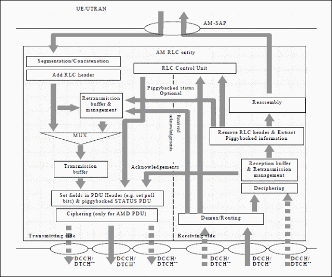
- AM (Acknowledged mode
Transparent Mode (TM) RLC
Services provided to upper layer
- Segmentation and reassembly
- Transfer of user data
- SDU discard
- If segmentation is configured by upper layers and a RLC SDU is larger than the TMD PDU size, the transmitting TM RLC entity segments RLC SDUs to fit the TMD PDU size without adding RLC headers.
- All the TMD PDUs carrying one RLC SDU are sent in the same TTI and no segment from another RLC SDU are sent in that TTI.
Unacknowledged Mode (UM) RLC Entity
Services provided to upper layer
- Segmentation and reassembly.
- Concatenation.
- Padding.
- Transfer of user data.
- Ciphering.
- Sequence number check.
- SDU discard.
Acknowledged Mode RLC Entity
Services provided to upper layer
- Segmentation and reassembly.
- Concatenation.
- Padding.
- Transfer of user data.
- Error correction.
- In-sequence delivery of upper layer PDUs.
- Duplicate detection.
- Flow Control.
- Protocol error detection and recovery.
- Ciphering.
- SDU discard.
RLC Error Correction
RLC Protocol Data Unit
Data PDUs
- TMD PDU (Transparent Mode Data PDU)
- UMD PDU (Unacknowledged Mode Data PDU)
- AMD PDU (Acknowledged Mode Data PDU)
Control PDUs
- Status PDU and Piggybacked STATUS PDU
- Reset PDU
- Reset-ACK PDU
TMD PDU (Transparent Mode Data PDU)
- The TMD PDU is used to transfer user data when RLC is operating in transparent mode.
- No overhead is added to the SDU by RLC.
- The data length is not constrained to be a multiple of 8 bits.
UMD PDU (Unacknowledged Mode Data PDU)
- The UMD PDU is used to transfer user data when RLC is operating in unacknowledged mode.
- The length of the data part shall be a multiple of 8 bits.
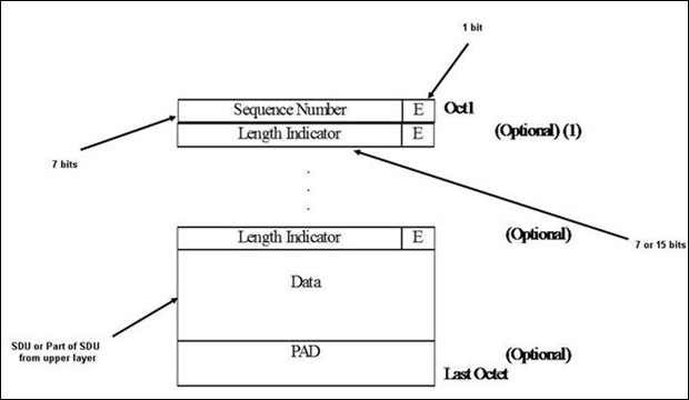
UMD PDU Header Details
Sequence Number
- Sequence number of UMD PDU encoded in binary.
- SN is of length 7 bits
- It is used for reassembly
Length Indicator
- LI is used to indicate the end of a SDU in a PDU.
- Lenth is 7 or 15 bits
E (Extension Bit)
E bit tells ”What there in the next field”
- If E = 0 : Next field is data or status PDU or a complete SDU
- If E 0 1 : Next filed is Length Indicator (LI) followed by extension bit (E).
AMD PDU (Acknowledged Mode Data PDU)
- The length of the data part shall be a multiple of 8 bits.
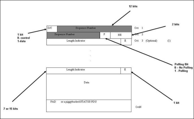
- The AMD PDU header consists of the first two octets, which contain the "Sequence Number".
AMD PDU Header Details
D/C
Indicates whether a data or control PDU
- If D/C = 1 : Its a data PDU
- If D/C = 0 : Its a control PDU
Sequence Number
- Length of sequence number is 12 bits i.e after SN reaches 4095 there will be a rollover.
- SN is used for retransmission and reassembly
P bit
Polling bit is used to request a status report from the receiver.
- If P = 0 : No status requested
- If P = 1 : Status requested
HE
Header Extension is of 2 bits and it indicates the next bit is data or ”Length Indicator” and E bit.
- If HE = 00 : Next octet is data
- If HE = 01 : Next octet is LI and E bit
- If HE = 10 : Next value is the data and last octet of the PDU is the last octet of the SDU.
- If HE = 11 : Reserved, discarded by protocol
Status PDU
- The length of the STATUS PDU shall be a multiple of 8 bits.
- Status PDU is used for transmission of status information.
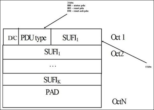
Status PDU Header Details
PDU Type
PDU type indicates the Control PDU type
- 000 : Status PDU
- 001 : Reset PDU
- 010 : Reset-Ack PDU
- 011 – 111 : Reserved
SUFI
Super-Field indicates which AMD PDUs are received correctly and which are missing.
SUFi has three sub-fields:
- Type
- Length
- Value
Reset and Reset-Ack PDU
RESET PDU
The RESET PDU is used in acknowledged mode to reset all protocol states, protocol variables and protocol timers of the peer RLC entity in order to synchronies the two peer entities.
RESET ACK PDU
The RESET ACK PDU is an acknowledgement to the RESET PDU.
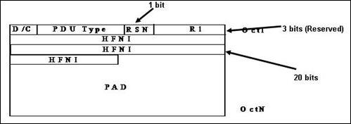
Reset/Reset-Ack PDU Header
RSN
- Reset Sequence Number is of 1 bit length.
- RSN is the sequence number of the transmitted RESET PDU.
- Initial value of this field is 0.
R1
- This field is used to make RESET/RESET-ACK PDU octet aligned.
- The value of R1 is 000.
HFNI
- Hyper Frame Number Indicator is of 2o bits.
- It is used to indicate the HFN to the peer entity.
- With the help of this HFN in UE and UTRAN can be synchronised.
RLC State Model
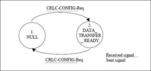
RLC TM State Model
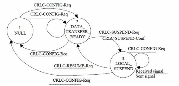
RLC UM State Model
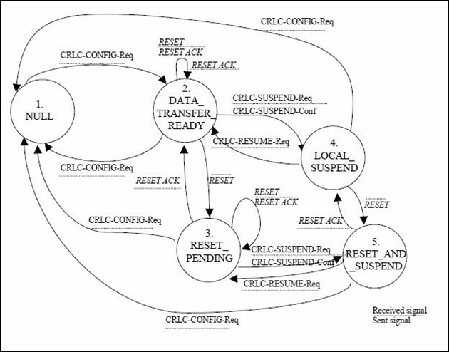
RLC AM State Model
Reference
Radio Link Control (RLC) protocol specification: 3GPP TS 25.322

Permalink
Good tutorial. Thanks for sharing.
Permalink
Good tutorial. Thanks for sharing.
Permalink
Very good information, but it is not only theory, we could have a closer contact with the applied?
Example: some software, existing equipment at nodes B, etc.. …
Greetings
Permalink
Very good information, but it is not only theory, we could have a closer contact with the applied?
Example: some software, existing equipment at nodes B, etc.. …
Greetings
Permalink
Thanks for sharing, Good tutorial, please explain in more implementation level.
Permalink
Thanks for sharing, Good tutorial, please explain in more implementation level.
Permalink
Thanks for your suggestion. I am trying to add slowly everything. So may be in coming days I will put some details. Still I already added tutorials on RLC LI and SUFIs. You can check those as well.
Permalink
Thanks for your suggestion. I am trying to add slowly everything. So may be in coming days I will put some details. Still I already added tutorials on RLC LI and SUFIs. You can check those as well.
Permalink
Thanks for the Tutorials.. these are really helpful, Can you add some more tutorials on LTE.
Permalink
Thanks for the Tutorials.. these are really helpful, Can you add some more tutorials on LTE.
Permalink
Very good tutorial.
Keep on doing the great work.
Thanks for sharing.
Permalink
Very good tutorial.
Keep on doing the great work.
Thanks for sharing.
Permalink
very good tutorial, but explanation on each states and terms are required…
thanx for sharing….
Permalink
Thanks for the comment.
We have added more information about RLC in other tutorials. But still if you need more info we can help. We will add some more RLC tutorials in coming days.
Permalink
Hi, Can anybody tell where is this protocol terminated in a mobile network?
a) PDSN
b) AAA
c) BSC/PCF
d) BTS
Permalink
Hi,
It will be great if you can ask the question the FORUMS. So that it will be easy to track down the questions.
http://www.3glteinfo.com/forums/
Check the above link.
Permalink
I have question about Length Indicator.
Length Indicator is 7bits or 15bits but how to identify the size of LI from message PUD?
Permalink
The size of the LI is configured by upper layer i.e. by RRC.
Permalink
Awesome note… really helpful
Permalink
tis is very help full link , tnx, looking for more topics overview
Permalink
Thanks Munna
Permalink
please share how to fix the LI(length indicator)
Permalink
Hi,
Please check the following tutorials for LI encoding and decoding
http://www.3glteinfo.com/umts-rlc-length-indicator-rlc-li-20090907
Permalink
Thanks for sharing.. good one.. (more info from Andrew Richards 🙂 )
Permalink
Permalink
Very interesting and useful.