What are soft and softer handover in 3G UMTS mobile system?
Handovers are an important part of every cellular communication system. They are used for providing mobility in cellular architectures. In UMTS systems different handover types have been introduced to cope also with other requirements as load control, coverage provisioning and offering quality of services.
Handover aims to provide continuity of mobile services to a user traveling over cell boundaries in a cellular infrastructure. For a user having an ongoing communication and crossing the cell edge, it is more favorable to use the radio resources in the new cell – also called the target cell because the signal strength perceived in the “old” cell worsens as the user penetrates the target cell.
The whole process of tearing down the existing connection in the current cell and establishing a new connection in the appropriate cell is called “handover”. The ability of a cellular network to perform efficient handovers is crucial to offer attractive services as real-time applications or streaming media as planned in third generation networks.
Especially in WCDMA two special types of handovers have been introduced; soft and softer handovers, allowing a mobile user to use 2 separate air interface channels when being in the overlapping area of two adjacent sectors.
Soft & Softer handovers are similar in techniques but there are some differences in both the techniques.
Softer Handover
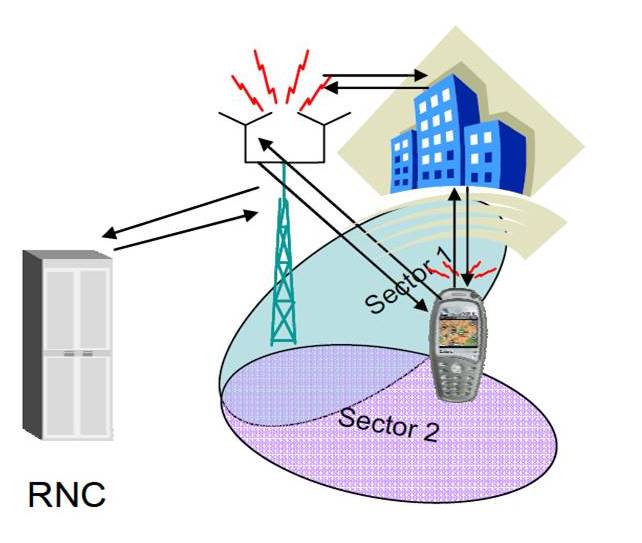
Softer handover is the situation where one base station receives two user signals from two adjacent sectors it serves. In the case of softer handover the base station receives 2 separated signals through multi-path propagation. Due to reflections on buildings or natural barriers the signal sent from the mobile stations reaches the base station from two different sectors.
The signals received during softer handover are treated similarly as multi-path signals. In the uplink direction the signals received at the base station are routed to the same rake receiver and then combined following the maximum ratio combining technique. In the downlink direction the situation is slightly different as the base station uses different scrambling codes to separate the different sectors it serves.
So it is necessary for the different fingers of the rake receiver in the mobile terminal to apply the appropriate de-spreading code on the signals received from the different sectors before combining them together.
Soft Handover
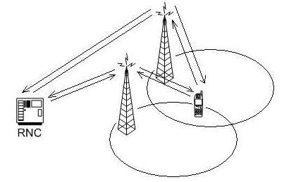
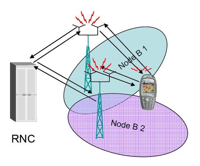
In the case of soft handover the mobile station is in the overlapping cell coverage area of two sectors belonging to different base stations.
In downlink direction the signals received from the two different base stations are combined using MRC Rake processing in the mobile station.
In the uplink direction the received signals can no longer be combined in the base station but are routed to the RNC. The combining follows a different principle; in the RNC the two signals are compared on a frame-by-frame basis and the best candidate is selected after each interleaving period; i.e. every 10, 20, 40 or 80ms. As the outer loop power control algorithm measures the SNR of received uplink signals at a rate between 10 and 100Hz, this information is used to select the frame with the best quality during the soft handover.
The Soft Handover procedure is composed of a number of single functions:
- Measurements
- Filtering of Measurements
- Reporting of Measurement results
- The Soft Handover Algorithm
- Execution of Handover
Soft Handover Algorithm
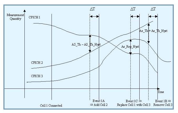
Soft handover in practice is a complex technique. The following example will describe soft handover for best case scenario.
Before describing the above scenario we need to know three important terms.
Active Set
User information is sent all the cell belongs to Active Set. In FDD, the cells in the active set are involved in soft handover. In TDD the active set always comprises one cell only. The UE shall only consider active set cells included in the variable CELL_INFO_LIST for measurement; i.e. active set cells not included in the CELL_INFO_LIST shall not be considered in any event evaluation and measurement reporting.
Monitored Set
Cells, which are not included in the active set, but are included in the CELL_INFO_LIST belong to the monitored set.
Detected Set
Cells detected by the UE, which are neither in the CELL_INFO_LIST nor in the active set belong to the detected set. Reporting of measurements of the detected set is only applicable to intra-frequency measurements made by UEs in CELL_DCH state.
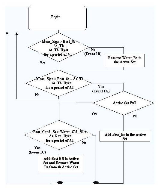
The above scenario can be devided into three different parts.
Radio Link Addition (Event 1A)
Event 1A is triggered when a primary CPICH enters the reporting range. This means when a cell is strong enough to enter into Active Set.
Radio Link Deletion (Event 1B)
Event 1B is triggered when a primary CPICH leaves the reporting range. This happens when a cell in active set become weak and needs to be removed from Active Set.
Combined Radio Link Addition & Deletion (Event 1C)
Event 1C is triggered when a non-active primary CPICH becomes better than an active primary CPICH. When this event is triggered a primary CPICH is removed from the Active Set and a new stronger cell is added into Active Set.
You can get information on other events in another article.

Permalink
Thanks Prashant. Another Valuable Tutorial.
Permalink
Thanks Jai.
Permalink
please share some doc on how mobile works after switching on.
Permalink