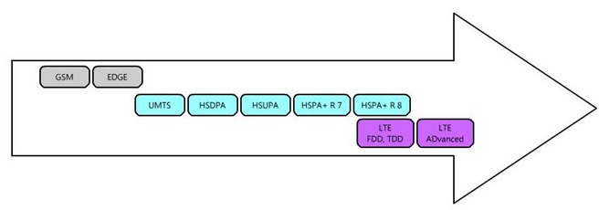
LTE stands for Long Term Evolution. The LTE project was initiated in November 2004 and the focus was on enhancing the Universal Terrestrial Radio Access (UTRA) and optimizing the 3GPP’s radio access architecture.
The most important objective of LTE is to achieve the following:
- Higher Bitrates (100 Mbps DL an 50 Mbps UL)
- Reduced delays in terms of connection establishment and transmission latency.
- Increase cell edge bit rate.
- Network optimization for packet data
- Simplified NW structure
- Lower cost per bit
- Frequency flexibility
- Seamless mobility between different radio access technologies
- Reasonable power consumption for UEs
Detailed Requirements
Peak data rate
- Instantaneous downlink peak data rate of 100 Mb/s within a 20 MHz downlink spectrum allocation (5 bps/Hz)
- Instantaneous uplink peak data rate of 50 Mb/s (2.5 bps/Hz) within a 20MHz uplink spectrum allocation)
Control-plane latency
- Transition time of less than 100 ms from a camped state, such as Release 6 Idle Mode, to an active state such as Release 6 CELL_DCH
- Transition time of less than 50 ms between a dormant state such as Release 6 CELL_PCH and an active state such as Release 6 CELL_DCH
Control-plane capacity
- At least 200 users per cell should be supported in the active state for spectrum allocations up to 5 MHz
User-plane latency
- Less than 5 ms in unload condition (ie single user with single data stream) for small IP packet
User throughput
- Downlink: average user throughput per MHz, 3 to 4 times Release 6 HSDPA
- Uplink: average user throughput per MHz, 2 to 3 times Release 6 Enhanced Uplink
Spectrum efficiency
- Downlink: In a loaded network, target for spectrum efficiency (bits/sec/Hz/site), 3 to 4 times Release 6 HSDPA )
- Uplink: In a loaded network, target for spectrum efficiency (bits/sec/Hz/site), 2 to 3 times Release 6 Enhanced Uplink
Mobility
- E-UTRAN should be optimized for low mobile speed from 0 to 15 km/h Higher mobile speed between 15 and 120 km/h should be supported with high performance
- Mobility across the cellular network shall be maintained at speeds from 120 km/h to 350 km/h (or even up to 500 km/h depending on the frequency band)
Coverage
- Throughput, spectrum efficiency and mobility targets above should be met for 5 km cells, and with a slight degradation for 30 km cells. Cells range up to 100 km should not be precluded.
Further Enhanced Multimedia Broadcast Multicast Service (MBMS)
- While reducing terminal complexity: same modulation, coding, multiple access approaches and UE bandwidth than for unicast operation.
- Provision of simultaneous dedicated voice and MBMS services to the user.
- Available for paired and unpaired spectrum arrangements.
Spectrum flexibility
- E-UTRA shall operate in spectrum allocations of different sizes, including 1.25 MHz, 1.6 MHz, 2.5 MHz, 5 MHz, 10 MHz, 15 MHz and 20 MHz in both the uplink and downlink. Operation in paired and unpaired spectrum shall be supported
- The system shall be able to support content delivery over an aggregation of resources including Radio Band Resources (as well as power, adaptive scheduling, etc) in the same and different bands, in both uplink and downlink and in both adjacent and non-adjacent channel arrangements. A “Radio Band Resource” is defined as all spectrum available to an operator
Co-existence and Inter-working with 3GPP Radio Access Technology (RAT)
- Co-existence in the same geographical area and co-location with GERAN/UTRAN on adjacent channels.
- E-UTRAN terminals supporting also UTRAN and/or GERAN operation should be able to support measurement of, and handover from and to, both 3GPP UTRAN and 3GPP GERAN.
- The interruption time during a handover of real-time services between E-UTRAN and UTRAN (or GERAN) should be less than 300 msec.
Architecture and migration
- Single E-UTRAN architecture
- The E-UTRAN architecture shall be packet based, although provision should be made to support systems supporting real-time and conversational class traffic
- E-UTRAN architecture shall minimize the presence of “single points of failure”
- E-UTRAN architecture shall support an end-to-end QoS
- Backhaul communication protocols should be optimised
Radio Resource Management requirements
- Enhanced support for end to end QoS
- Efficient support for transmission of higher layers
- Support of load sharing and policy management across different Radio Access Technologies
Complexity
- Minimize the number of options
- No redundant mandatory features
Standardization
In 2007, E-EUTRA progressed from feasibility study stage to first approved Technical specification.
LTE Specifications Web Link:
http://www.3gpp.org/ftp/Specs/html-info/36-series.htm
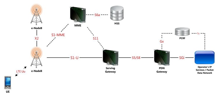
LTE System Architecture
eNodeB
EPS (Evolved Packet System) eNodeB covers the following functionalities:
- Functions for Radio Resource Management
- Radio Bearer Control
- Radio Admission Control
- Connection Mobility Control
- Dynamic allocation of resources to UEs, both in the uplink and in downlink.
- IP header compression and encryption of user data.
- Selection of MME at UE attachment
- Routing of user plane data towords Serving Gateway
- Scheduling and transmission of paging messages
- Scheduling and transmission of broadcast message
- Measurements for mobility and scheduling
MME (Mobility Management Entity)
- NAS signalling
- NAS signalling security
- Inter CN node signalling for mobility between 3GPP access networks (terminating S3)
- UE Reachability in ECM-IDLE state (including control and execution of paging retransmission)
- Tracking Area list management
- PDN GW and Serving GW selection
- MME selection for handovers with MME change
- SGSN selection for handovers to 2G or 3G 3GPP access networks
- Roaming (S6a towards home HSS)
- Authentication
- Authorization
- Bearer management functions including dedicated bearer establishment
- Lawful Interception of signalling traffic
- Warning message transfer function (including selection of appropriate eNB)
- UE Reachability procedures.
S-GW (Serving Gateway)
The Serving GW is the gateway which terminates the interface towards E-UTRAN.
For each UE associated with the EPS, at a given point of time, there is a single Serving GW.
The Serving Gateway covers the following functionalities:
- the local Mobility Anchor point for inter-eNodeB handover;
- sending of one or more “end marker” to the source eNodeB, source SGSN or source RNC immediately after switching the path during inter-eNodeB and inter-RAT handover, especially to assist the reordering function in eNodeB.
- Mobility anchoring for inter-3GPP mobility (terminating S4 and relaying the traffic between 2G/3G system and PDN GW);
- ECM-IDLE mode downlink packet buffering and initiation of network triggered service request procedure;
- Lawful Interception;
- Packet routing and forwarding;
- Transport level packet marking in the uplink and the downlink, e.g. setting the DiffServ Code Point, based on the QCI of the associated EPS bearer;
- Accounting for inter-operator charging. For GTP-based S5/S8, the Serving GW generates accounting data per UE and bearer;
NOTE: Connectivity to a GGSN is not supported.
PDN GW (PDN Gateway)
The PDN GW is the gateway which terminates the SGi interface towards the PDN.
If a UE is accessing multiple PDNs, there may be more than one PDN GW for that UE, however a mix of S5/S8 connectivity and Gn/Gp connectivity is not supported for that UE simultaneously.
PDN GW functions include for both the GTP-based and the PMIP-based S5/S8:
- Per-user based packet filtering (by e.g. deep packet inspection);
- Lawful Interception;
- UE IP address allocation;
- Transport level packet marking in the uplink and downlink, e.g. setting the DiffServ Code Point, based on the QCI of the associated EPS bearer;
- Accounting for inter-operator charging;
- UL and DL service level charging (e.g. based on SDFs defined by the PCRF, or based on deep packet inspection defined by local policy);
- Interfacing OFCS through according to charging principles and through reference points
- UL and DL service level gating control
- UL and DL service level rate enforcement (e.g. by rate policing/shaping per SDF);
- UL and DL rate enforcement based on APN-AMBR (e.g. by rate policing/shaping per aggregate of traffic of all SDFs of the same APN that are associated with Non-GBR QCIs);
- DL rate enforcement based on the accumulated MBRs of the aggregate of SDFs with the same GBR QCI (e.g. by rate policing/shaping);
- DHCPv4 (server and client) and DHCPv6 (client and server) functions;
- The network does not support PPP bearer type in this version of the specification. Pre-Release 8 PPP functionality of a GGSN may be implemented in the PDN GW;
- packet screening.
Reference
- Evolved Universal Terrestrial Radio Access (E-UTRA) and Evolved Universal Terrestrial Radio Access Network (E-UTRAN); http://www.3gpp.org/ftp/Specs/html-info/36300.htm
- 4G: LTE/LTE-Advanced for Mobile Broadband
- LTE – The UMTS Long Term Evolution: From Theory to Practice
- An Introduction to LTE: LTE, LTE-Advanced, SAE and 4G Mobile Communications


Permalink
Can you verify something for me? I have read the widely quoted number of 100Mbps for 20MHz and seen another number of 326Mbps with the optimal antenna design. However, I believe that this is total capacity for a given sector. Is this correct?
If so, if I have an installation in a dense urban environment where there are up to the full capacity of users (I believe 400 for 20MHz 4×4 antenna) then the capacity available for one user would be 326/200 or 1.8 Mbps. Of course, it would be even lower as distance from the cell site increases and I assume that it faces the typical capacity fall-off as usage nears the maximum capacity.
Thanks
Permalink
your matter helps me a lot i am doing research on Optimization of MIMO systems. Ca you suggest some thing in that direction
bhoop_sharma@yahoo.com
Permalink
Useful blog website, keep me personally through searching it, I am seriously interested to find out another recommendation of it.
Permalink
can u please tell me how usim 3g context authentication differe from LTE authentication
Permalink
One of our contributor is preparing a new article on this topic. You will get some details on this in coming days.
Permalink
Thanks 🙂
Permalink
hi
can u plz provide me a full detailed material on LTE so i can prepare myself for a interview
thnanks
regards
anuj
Permalink
Hi We are tryong to put new materials on LTE. But it will take some time.
Permalink
Permalink