What is carrier aggregation and how this will help in improving bandwidth and throughput?
ITU set specific requirements for IMT Advanced compliant technology should fulfill. Some of these requirements include at least 40 MHz bandwidth, peak spectral efficiency of 15 bit/s/Hz in downlink and 6.75 bit/s/Hz in uplink and control plane and user plane latency of less than 100 and 10 ms respectively. Carrier aggregation is supported for both FDD and TDD.
Carrier aggregation is a LTE Advanced feature to increase aggregate bandwidth in order to improve data throughput in 4G mobile communication systems. Carrier aggregation in LTE was first introduced in 3GPP release 10 and further improvements are ongoing in Release 11 and onward. To make carrier aggregation backward compatible carriers used in this new feature are R8/R9 carriers.
- A Rel-10 UE with reception and/or transmission capabilities for CA can simultaneously receive and/or transmit on multiple Component Carriers (CCs) corresponding to multiple serving cells.
- A Rel-8/9 UE can receive on a single Component Carrier and transmit on a single Component Carrier corresponding to one serving cell only.

Carrier Aggregation is supported for both contiguous and non-contiguous Component Carriers with each Component Carrier limited to a maximum of 110 Resource Blocks in the frequency domain using the Rel-8/9 numerology.
- The number of DL Component Carriers that can be configured depends on the DL aggregation capability of the UE.
- The number of UL Component Carriers that can be configured depends on the UL aggregation capability of the UE.
- It is not possible to configure a UE with more UL Component Carriers than DL Component Carriers.
- In typical TDD deployments, the number of Component Carriers and the bandwidth of each Component Carrier in UL and DL is the same.
The spacing between centre frequencies of contiguously aggregated CCs shall be a multiple of 300 kHz. This is in order to be compatible with the 100 kHz frequency raster of Rel-8/9 and at the same time preserve orthogonality of the subcarriers with 15 kHz spacing.
Carrier Aggregation in Layer 2
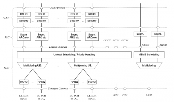
In case of Carrier Aggregation the multi-carrier nature of the physical layer is only exposed to the MAC layer for which one HARQ entity is required per serving cell.
In both uplink and downlink, there is one independent hybrid-ARQ entity per serving cell and one transport block is generated per TTI per serving cell in the absence of spatial multiplexing. Each transport block and its potential HARQ retransmissions are mapped to a single serving cell.
The reception timing difference at the physical layer of DL assignments and UL grants for the same TTI but from different serving cells (e.g. depending on number of control symbols, propagation and deployment scenario) does not affect MAC operation. A UE should cope with a relative propagation delay difference up to 30 microseconds among the component carriers to be aggregated in inter-band non-contiguous CA. This implies that a UE should cope with a delay spread of up to 31.3 micro seconds among the component carriers monitored at the receiver, since the BS time alignment is specified to be up to 1.3 microseconds.
Layer 2 Structure for downlink with CA configured

Layer 2 Structure for uplink with CA configured

RRC Carrier Aggregation
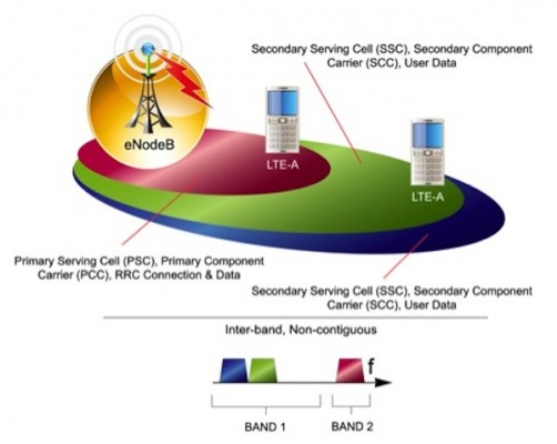
When CA is configured, the UE only has one RRC connection with the network. At RRC connection establishment/reestablishment/handover, one serving cell provides the NAS mobility information (e.g. TAI), and at RRC connection reestablishment/handover, one serving cell provides the security input. This cell is referred to as the Primary Cell (PCell).
In the downlink, the carrier corresponding to the PCell is the Downlink Primary Component Carrier (DL PCC) while in the uplink it is the Uplink Primary Component Carrier (UL PCC).
Depending on UE capabilities, Secondary Cells (SCells) can be configured to form together with the PCell a set of serving cells. In the downlink, the carrier corresponding to an SCell is a Downlink Secondary Component Carrier (DL SCC) while in the uplink it is an Uplink Secondary Component Carrier (UL SCC).

Permalink
Do you know any carrier aggregation strategies to follow for Interband CA ? Any specific Pros and cons as well ?
Permalink
@36faf73f15b7787c0cdf9182bf49b38a:disqus Thanks for the question. Interband CA is a very challenging area. I will try to make an article on that.
Permalink
Is there a relation between LTE UE category and aggregated bandwidth?
For example: Cat 6 UE only support max aggregated bandwidth of 40 MHz?
Is it true?
Is there a 3gpp reference for this?
Permalink
Hi Arul,
Check all carrier aggregation details from 3GPP TR 36.808.
If you are interested check these specifications for more details. If you have any question send me an email : contact@3glteinfo.com
Here are the specifications for carrier aggregation study:
TR 36.808 Evolved Universal Terrestrial Radio Access (E-UTRA); Carrier Aggregation; Base Station (BS) radio transmission and reception
TR 36.814 Evolved Universal Terrestrial Radio Access (E-UTRA); Further advancements for E-UTRA physical layer aspects
TR 36.815 Further Advancements for E-UTRA; LTE-Advanced feasibility studies in RAN WG4
TR 36.823 Evolved Universal Terrestrial Radio Access (E-UTRA); Carrier Aggregation Enhancements; UE and BS radio transmission and reception
TR 36.912 Feasibility study for Further Advancements for E-UTRA (LTE-Advanced)
TR 36.913 Requirements for further advancements for Evolved Universal Terrestrial Radio Access (E-UTRA) (LTE-Advanced)
TS 36.101 Evolved Universal Terrestrial Radio Access (E-UTRA); User Equipment (UE) radio transmission and reception
TS 36.211 Evolved Universal Terrestrial Radio Access (E-UTRA); Physical channels and modulation
TS 36.212 Evolved Universal Terrestrial Radio Access (E-UTRA); Multiplexing and channel coding
TS 36.213 Evolved Universal Terrestrial Radio Access (E-UTRA); Physical layer procedures
TS 36.300 Evolved Universal Terrestrial Radio Access (E-UTRA) and Evolved Universal Terrestrial Radio Access Network (E-UTRAN); Overall description; Stage 2
Permalink
in carrier Aggregation
if p cell handover happened then all scell get release or they add to target cell or new process will happened
or at the time of handover in A6 scell transfer to other scell but signalling is at same