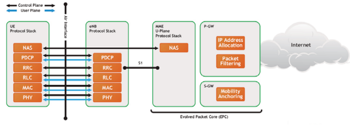
This tutorial describes the specific details of the LTE MAC layer or the Medium Access Control protocol. MAC is a radio network protocol which resides both in the UE and in the E-UTRAN. Also, it should be noted that MAC protocol is available for both User plane and also for the control plane.
RRC (Radio Resource Control) protocol is in control of the configuration of MAC that means RRC decides how MAC will behave. For example RRC tells MAC to configure a specific PDU size.
MAC Architecture

E-UTRA defines two MAC entities; one in the UE and one in the E-UTRAN. Here is how it looks for user plane and control plane.
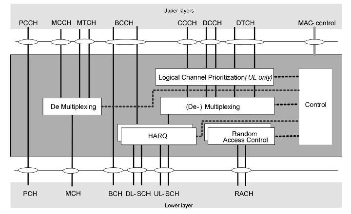
The MAC layer is composed of a Hybrid Automatic Repeat request (HARQ) entity, a multiplexing/de-multiplexing entity, a logical channel prioritization entity, and a control entity.
Multiplexing and de-multiplexing entity
The multiplexing and de-multiplexing entity is in charge of composing and decomposing the MAC PDUs and performs (de-) multiplexing of data from several logical channels into/from one transport channel.
Logical channel prioritization entity
When the radio resources for a new transmission are allocated, the logical channel prioritization entity instructs the multiplexing and de-multiplexing entity to generate MAC PDUs from the MAC SDUs.
The logical channel prioritization entity also decides how much data from each configured logical channel should be included in each MAC PDU whenever radio resource for a new transmission is available. As stated above, this decision is delivered to the multiplexing and demultiplexing entity.
HARQ entity
The HARQ entity performs the transmit HARQ operation and the receive HARQ operation. The transmit HARQ operation includes transmission of transport blocks and, if necessary, retransmission of the transport blocks, and, if configured, reception and processing of HARQ ACK/NACK signaling. The receive HARQ operation includes reception of transport blocks, combining and decoding of the received transport blocks and, if configured, generation of HARQ ACK/NACK signaling.
Control entity
The control entity is responsible for a number of functions including DRX, resource requests, alignment of the uplink timing, power headroom reporting, and so on.
The Random Access (RA) procedure is used to request uplink radio resource to transmit uplink data when the UE does not have any dedicated uplink transmission resource, or to respond to the network’s request.
MAC Layer Functions
MAC layer performs the following functions. Not all of these are performed by UE and eNodeB. Also, it should be noted that some of these functions are available in uplink and other in downlink.
What functions are supported
- Mapping between logical channels and transport channels
- Multiplexing of MAC SDUs from one or different logical channels onto transport blocks (TB) to be delivered to the physical layer on transport channels
- Demultiplexing of MAC SDUs from one or different logical channels from transport blocks (TB) delivered from the physical layer on transport channels
- Scheduling information reporting
- Error correction through HARQ
- Priority handling between UEs by means of dynamic scheduling
- Priority handling between logical channels of one UE
- Logical Channel
- Transport format selection
Transport Channels and Logical Channel
Channel structure in LTE is similar to that of UMTS but it is much simplified in LTE and the numbers of transport channels and logical channels are also lowered. Unlike UTRA/HSPA, LTE is based entirely on shared and broadcast channels and contains no dedicated channels carrying data to specific UEs. This improves the efficiency of the radio interface and can support dynamic resource allocation between different UEs depending on their traffic/QoS requirements and their respective channel conditions.
Logical channels provide services at the SAP between MAC and RLC layers, while transport channels provide services at the SAP between MAC and PHY layers.
Logical Channels
Logical channels are available between MAC and RLC layers and are used by MAC to provide services to RLC. Logical channels tells what type of information is transferred. Depending on the traffic types broadly the logical channels can be of two types:- logical control channels and logical traffic channels.
Here are the different logical channels in LTE.
Logical Control Channels
Broadcast Control Channel (BCCH): BCCH is a downlink channel used to carry broadcast system control information (e.g. SIBs)
Multicast Control Channel (MCCH): A point-to-multipoint downlink channel used for transmitting control information to UEs in the cell. It is only used by UEs that receive multicast/broadcast services.
Paging Control Channel (PCCH): PCCH is a downlink control channel to carry paging information such as control information during mobile-terminated call.
Common Control Channel (CCCH): CCCH is used to carry control information between UE and network when RRC connection is not available. CCCH is a bidirectional channel. CCCH is used during random access procedure.
Dedicated Control Channel (DCCH): A point-to-point, bi-directional channel that transmits dedicated control information between a UE and the network. This channel is used when the RRC connection is available, that is, the UE is attached to the network.
Logical Traffic Channels
Logical traffic channels carry user plane information.
Dedicated Traffic Channel (DTCH): A point-to-point, bi-directional channel used between a given UE and the network. It can exist in both uplink and downlink.
Multicast Traffic Channel (MTCH): A unidirectional, point-to-multipoint data channel that transmits traffic data from the network to UEs. It is associated with the multicast/broadcast service.
Transport Channels
Transport channels exist between MAC and physical layer. The transport channels are used by PHY to offer services to its upper layer i.e. MAC.
A transport channel is basically characterized by how and with what characteristics data is transferred over the radio interface, that is, the channel coding scheme, the modulation scheme, and antenna mapping.
Compared to WCDMA/UMTS, in LTE there are no dedicated transport channels exists. Transport channels can be of two types depending upon the direction of use, downlink transport channels and uplink transport channels.
Downlink Transport Channels
Broadcast Channel (BCH): BCH is associated with the BCCH logical channel and is used to broadcast system information over the entire coverage area of the cell. BCH has a predefined transport format.
Downlink Shared Channel (DL-SCH): DL-SCH is used to transfer both downlink traffic data and control data. DL-SCH supports HARQ, dynamic link adaptation, dynamic and semi-persistent resource allocation, UE discontinuous reception, and multicast/broadcast transmission. DL-SCH can be broadcast in the entire cell.
Paging Channel (PCH): Paging channel is only associated with PCCH logical channel. PCH channel supports discontinuous reception (DRX) to enable UE power saving and can be used in the entire cell coverage area.
Multicast Channel (MCH): Associated with MCCH and MTCH logical channels for the multicast/broadcast service. It supports Multicast/Broadcast Single Frequency Network (MBSFN) transmission, which transmits the same information on the same radio resource from multiple synchronized base stations to multiple UEs.
Uplink Transport Channels
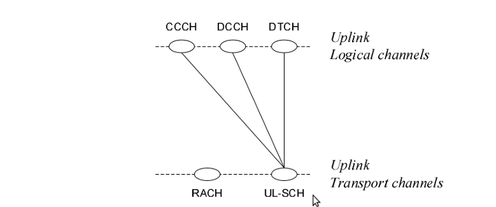
Uplink Shared Channel (UL-SCH): UL-SCH works similar as DL-SCH but in uplink. It supports HARQ, both dynamic and semi-static resource allocation, dynamic link adaptation and beamforming. It can be associated to CCCH, DCCH, and DTCH logical channels.
Random Access Channel (RACH): RACH is not associated with any logical channels and is used for transmitting small amount of data, for example RACH can be used in case of inital access.
Channel Mapping
Uplink Channel Mapping

In uplink following connections between logical channels and transport channels can exist.
CCCH can be mapped to UL-SCH
DCCH can be mapped to UL- SCH
DTCH can be mapped to UL-SCH
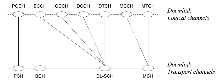
Downlink Channel Mapping

In downlink following channel mapping can be possible:
BCCH can be mapped to BCH
BCCH can be mapped to DL-SCH
PCCH can be mapped to PCH
CCCH can be mapped to DL-SCH
DCCH can be mapped to DL-SCH
DTCH can be mapped to DL-SCH
MTCH can be mapped to MCH
MCCH can be mapped to MCH
MAC Procedures Overview
MAC layer in LTE can perform the following procedures:
- Random Access Procedure
- DL-SCH Data Transfer
- UL-SCH Data Transfer
- PCH Reception
- BCH Reception
- Discontinuous Reception
- MAC Reconfiguration
- MAC Reset
NOTE: Important procedures will be discussed in separate sections.
MAC PDU – Protocol Data Unit
A MAC PDU consists of a MAC header, zero or more MAC Service Data Units (MAC SDU), zero, or more MAC control elements, and optionally padding.
MAC PDUs are byte aligned means they are multiple of 8 bits. MAC headers and SDUs are of variable sizes. MAC SDUs (RLC PDUs) are also byte aligned.

A MAC PDU subheader consists of the six header fields R/R/E/LCID/F/L but for the last subheader in the MAC PDU and for fixed sized MAC control elements.
The last subheader in the MAC PDU and subheaders for fixed sized MAC control elements consist solely of the four header fields R/R/E/LCID.
A MAC PDU subheader corresponding to padding consists of the four header fields R/R/E/LCID.
MAC PDU subheaders have the same order as the corresponding MAC SDUs, MAC control elements and padding.
MAC control elements are always placed before any MAC SDU.
NOTE: A maximum of one MAC PDU can be transmitted per TB per UE. A maximum of one MCH MAC PDU can be transmitted per TTI.

Permalink
Permalink
Thank you so much for sharing this valuable info…………………
Permalink
Thanks for simplifying MAC layer description
Permalink
What are the bits R/R/E/LCID/F/L in the MAC sub header description?
Permalink
please help with providing the decoder MAC PDU.
Permalink
please help me. i am really in a bad situation.
Begging your pardon. I will catch your legs
Permalink
Thanks for this post click here for more information.
Permalink
Why LCP used in UL not in DL.